Engineering Perspective on automatic ball valve Performance
Selecting the right automatic ball valve is rarely a matter of picking a single component — it is a system-level decision that touches actuator sizing, seat material, pressure class, and the specific duty cycle a facility expects from its piping network. Engineers evaluating an automatic ball valve for a new installation typically start with three questions: what medium will pass through the valve, what pressure and temperature range must the valve tolerate, and how many actuation cycles per day are expected. These three answers largely determine whether a standard quarter-turn design, a heavy-duty motorized ball valve , or a specialized automatic weld end ball valves configuration is the correct fit.
Because ball valves rely on a rotating spherical disc rather than a sliding gate or a swinging disc, they offer a tight shutoff with minimal pressure drop across the full bore. When automation is added, this mechanical simplicity becomes an advantage: fewer moving parts inside the wetted section means fewer points of failure once an electric or pneumatic actuator takes over the opening and closing motion. The sections below examine the mechanical, material, and operational factors that separate a reliable automated valve installation from one that requires frequent servicing.
Product Category Snapshot
The automation market for ball valves is not a single product line — it spans several distinct configurations, each suited to a different piping challenge. The card summary below outlines the four categories referenced most frequently by piping designers and maintenance teams.
Standard Automation
automatic ball valve
General-purpose flow shutoff for water, air, and mild chemical lines. Typically flanged or threaded, driven by an electric or pneumatic actuator with 90-degree rotation.
Fire Protection
automatic ball drip valve
Installed at low points of dry-pipe sprinkler systems to release condensate automatically and prevent freeze damage or corrosion buildup inside the pipe run.
High-Pressure Piping
automatic weld end ball valves
Butt-weld connections eliminate gasket interfaces entirely, making this configuration the preferred choice for high-pressure steam, oil, and long-distance transmission lines.
Electric Drive
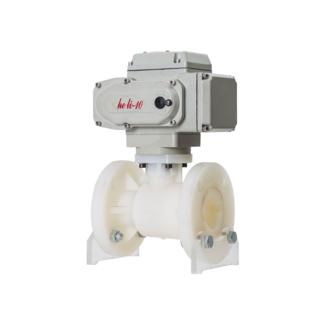
motorized ball valve
Combines a geared electric actuator with position feedback, allowing integration into building automation panels, pump station controls, or remote monitoring platforms.
Actuation Mechanics: How Does an Automatic Valve Work
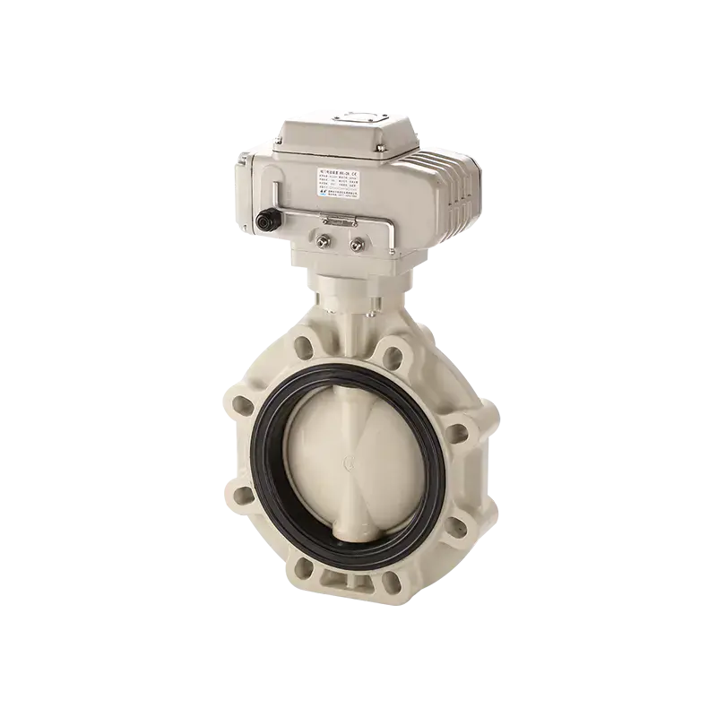
At the core of every automated ball valve sits a coupling between the actuator output shaft and the valve stem. When a control signal — whether a dry contact, a 4-20mA loop, or a Modbus command — reaches the actuator, an internal motor drives a reduction gear train. This gear train converts high-speed, low-torque motor rotation into slow-speed, high-torque stem rotation, which is exactly what a ball valve needs to break static friction at the seat and swing the ball through ninety degrees.
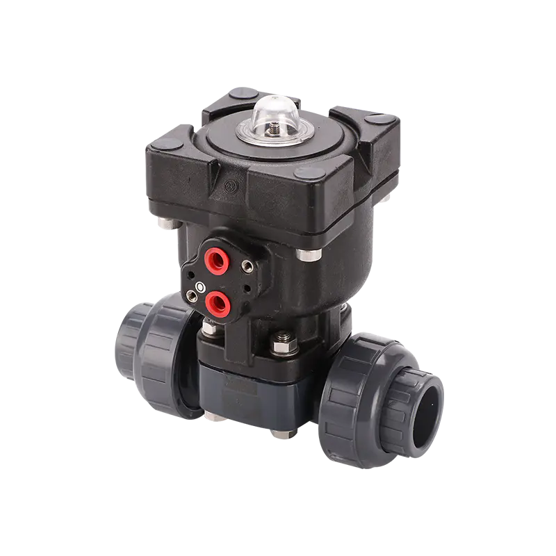
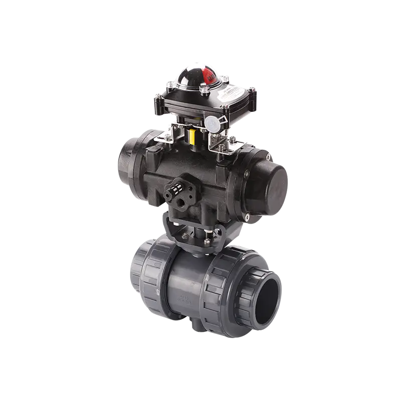
Two limit switches, mechanically or electronically set, tell the control system when the valve has reached full open or full closed position. Many installations also include a torque switch, which interrupts power to the motor if resistance exceeds a preset threshold — protecting the gear train from damage if the valve seizes due to debris or seat wear. On pneumatic versions, compressed air replaces the electric motor, and a spring-return mechanism can be added so the valve automatically moves to a fail-safe position if air supply is lost, a feature frequently specified for isolation valves on hazardous service lines.
The distinction between electric and pneumatic drive matters most in facilities without an existing compressed air network — in those cases a motorized ball valve avoids the cost of installing air lines, while pneumatic actuation remains preferred in explosive atmosphere zones where electric sparking risk must be minimized.
Actuator Torque Output Across Valve Sizes
Torque output does not scale linearly with valve diameter — seat friction increases with the square of the ball diameter, which is why larger valves require disproportionately higher actuator torque. The curve below illustrates the typical torque demand pattern seen across a standard product range at rated pressure.
Approximate breakaway torque curve for a mid-pressure carbon steel ball valve line, DN15 through DN300.
Undersizing an actuator against this curve is one of the most common design errors in automated piping projects. An actuator selected purely on nominal bore without checking the manufacturer's rated pressure differential can stall on the first operation after the valve has sat idle, since seat compression increases resistance over time even without corrosion.
Material and Pressure Reference
Body material and seat compound selection directly affect service life, and the correct combination depends heavily on the fluid being controlled. The reference table below groups common configurations by service type.
Body Material
Seat Material
Typical Pressure Class
Recommended Service
Stainless Steel 304
PTFE / RPTFE
Class 150 / PN16
Potable water, mild chemicals
Stainless Steel 316
RPTFE
Class 300 / PN25
Seawater, corrosive fluids
Carbon Steel WCB
RPTFE / PEEK
Class 300–600
Steam, oil transmission lines
Forged Steel A105
PEEK / Metal Seat
Class 600–900
automatic weld end ball valves, high pressure
Brass / Bronze
PTFE
PN16
HVAC, general water distribution
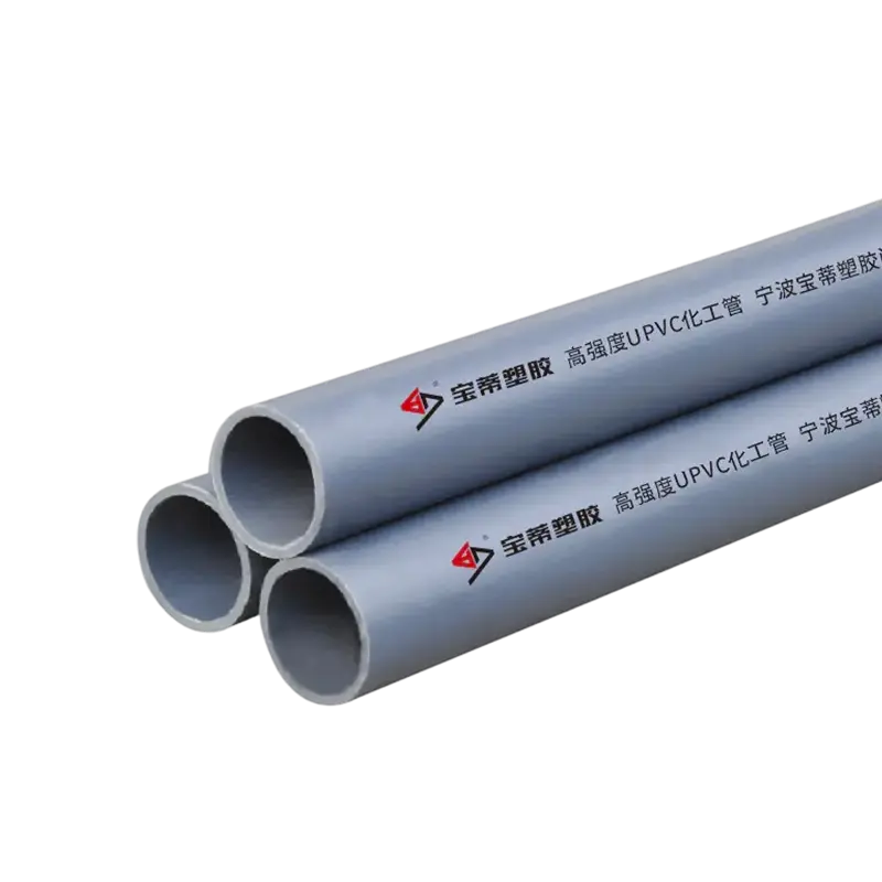
PVC / CPVC
EPDM
150 PSI
Chemical drainage, irrigation
Manual Versus Motorized Response Time
One of the strongest arguments for automation is response speed during upset conditions. A manually operated valve depends entirely on an operator reaching the valve location, while a motorized ball valve can respond to a control signal within seconds, regardless of where personnel are standing at the time.
DN25 Manual
45–90 sec
DN25 Motorized
6 sec
DN150 Manual
3–5 min
DN150 Motorized
15 sec
This gap widens further on larger diameters, which is precisely why critical isolation points in tank farms, boiler feed lines, and pump stations are rarely left on manual operation once a facility scales past a certain throughput.
automatic ball drip valve and Dry-Pipe System Behavior
Dry-pipe fire suppression systems fill piping with pressurized air rather than water, holding water back at the system riser until a fire event triggers the sprinkler heads. The challenge with this design is condensation: temperature swings inside the pipe cause moisture to accumulate at low points, and if that moisture is not removed, it can freeze in cold climates or corrode the pipe wall from the inside over years of operation.
An automatic ball drip valve solves this by sitting at the lowest elevation point of the branch line. During normal standby conditions, with no differential pressure across the valve, an internal ball or poppet remains lifted off its seat by gravity or a light spring, allowing accumulated condensate to weep out continuously. The moment the system pressurizes — either during testing or an actual fire event — differential pressure forces the internal element against its seat, sealing the line so air pressure is not lost through the drip point.
Where additional protection against backflow is required, an automatic ball drip check valve adds a secondary sealing element that prevents outside air or moisture from being drawn back into the system during pressure fluctuations. This is particularly relevant in exposed piping runs, such as parking garages or unheated warehouses, where the differential between inside and outside temperature is significant. A related variant, the automatic ball drip drain valve , is sized specifically for higher condensate volumes and is commonly specified on systems with long horizontal branch runs where multiple low points feed into a single collection line.
Fire code authorities generally require these drip valves to be installed with a visible discharge point directed away from walkways, and maintenance personnel are expected to verify free operation during annual dry-pipe system inspections, since a stuck or corroded drip valve is one of the more common causes of trapped water discovered during pre-action testing.
Frequently Raised Technical Questions
Can you automate a ball valve that was originally manual?
In most cases, yes. Standard ISO 5211 mounting pads on the valve bonnet are designed to accept a bolt-on actuator without modifying the valve body itself. The retrofit process involves removing the manual handle, confirming the actuator's torque rating exceeds the valve's breakaway torque at operating pressure, and matching the mounting flange dimensions before installation.
What are the common problems with motorized ball valves in field service?
Field data from maintenance logs points to a recurring pattern: moisture ingress into the actuator housing due to a failed gasket, limit switch drift causing the valve to stop short of full travel, and seat hardening in high-temperature service that increases required torque over time. Less frequently, wiring terminal corrosion in outdoor installations interrupts the control signal entirely, which is why IP66 or IP67 rated enclosures are specified for any exposed installation.
How long should a motorised valve last before major overhaul?
Actuator gearboxes are typically rated for a defined number of full-stroke cycles rather than a calendar duration — commonly in the range of tens of thousands of cycles for standard-duty units. Translated into service years, a valve cycling a few times per day in a moderate environment can reasonably reach eight to twelve years before gearbox or seal replacement becomes necessary, while units in continuous modulating service wear considerably faster.
How to choose the right motorized ball valve for a specific line?
Selection should proceed in a fixed order: confirm line size and pressure class first, then select body and seat material against the fluid chemistry chart, then calculate actuator torque with a safety margin above the seat breakaway figure, and finally match the control signal type to the existing automation panel. Skipping the torque margin step is the single most frequent cause of premature actuator failure reported by maintenance teams.
What is another name for a ball valve used in technical specifications?
In specification documents, the ball valve is sometimes referred to as a quarter-turn valve, a term describing the ninety-degree rotation needed to move between fully open and fully closed. Some regional standards also group it under the broader rotary valve category alongside butterfly and plug valves.
What are the disadvantages of ball valves compared with other valve types?
Ball valves are not well suited to fine flow throttling — the flow characteristic across partial opening is nonlinear, which causes accelerated seat wear if used for continuous modulation rather than simple on-off duty. Larger diameters also carry more weight and higher actuator cost than an equivalent butterfly valve, and cavity-filling seat designs can trap process fluid if not specified with a self-draining ball profile in food or pharmaceutical lines.
Production and Quality Verification Process
Every automated valve leaving the production line passes through a sequence of mechanical and pressure checks before it is cleared for shipment. Casting or forging traceability is recorded first, followed by dimensional inspection against the relevant flange standard. The valve body then undergoes hydrostatic shell testing, typically at 1.5 times the rated working pressure, to confirm there is no porosity or weld defect capable of leaking under service load.
Seat sealing performance is verified separately through a low-pressure air seat test, since a body that passes hydrostatic testing can still leak internally across the ball-to-seat interface if machining tolerances drift. On weld-end configurations, additional radiographic or dye-penetrant inspection of the weld preparation area is performed prior to final assembly, given that automatic weld end ball valves rely entirely on the weld joint integrity rather than a gasketed connection.
Material Certification
Mill test reports are cross-checked against the specified alloy grade for both body castings and stem forgings before assembly begins.
Actuator Cycle Testing
Each assembled unit is run through repeated open-close cycles on a test bench to confirm torque switch calibration and limit switch alignment.
Pressure Verification
Shell and seat testing follows API 598 or equivalent regional standards, with pressure held for a defined dwell time to detect slow leaks.
Final Dimensional Check
Face-to-face length, bolt circle diameter, and bore alignment are measured against tolerance charts prior to packaging.
Application Environments
Water and Wastewater Treatment
Automated shutoff on filtration lines and chemical dosing skids, where remote actuation reduces the need for personnel to enter confined treatment areas.
HVAC and Building Services
Zone isolation on chilled water and heating loops, allowing a building management system to control temperature zones without manual valve access.
Oil, Gas and Petrochemical
High-pressure isolation using weld-end connections on pipelines where gasketed joints would introduce unacceptable leak risk over long service intervals.
Fire Protection Systems
Dry-pipe condensate management through drip and drip-check valve installations positioned at every low point of the sprinkler branch network.
Power Generation
Boiler feedwater and steam line isolation where actuator response time directly affects plant safety shutdown sequences.
Food and Beverage Processing
Sanitary-profile automated valves on CIP (clean-in-place) circuits, selected for self-draining ball geometry and smooth internal surface finish.
Installation and Maintenance Checklist
Correct commissioning has a direct effect on long-term reliability. The following points are commonly reviewed during pre-startup inspection of an automated valve installation:
Confirm actuator torque rating exceeds valve breakaway torque with a minimum 25 percent margin.
Verify flow direction arrow on the body aligns with actual pipeline flow, particularly on check-integrated designs.
Support valve weight independently on larger diameters rather than relying on pipe hangers alone.
Cycle the valve manually before powering the actuator to confirm free rotation of the ball.
Set and record limit switch positions after installation, not solely on bench-test values.
Inspect drip valve discharge points on dry-pipe systems annually, before seasonal temperature swings.
Long-Term Reliability of Automated Valve Systems
Reliability in automated ball valve service comes down to matching the mechanical design to the actual duty cycle rather than the nominal pipe size alone. A valve correctly sized for torque, seat material, and pressure class, paired with an actuator rated for the expected cycle frequency, will consistently outperform a generically selected unit even when both carry the same catalog dimensions. For facilities managing dry-pipe fire protection, HVAC zoning, or high-pressure transmission lines, the combination of correct material selection, verified factory testing, and disciplined installation practice is what ultimately determines whether an automatic ball valve delivers a decade of dependable service or requires early replacement.